“Widowmaker” refers to amps that can kill you because they are not grounded and can, in fact, put 117 volts AC through your body.
Typically these are amps that do not have a power transformer. The tube heaters on these are wired in series to effectively reduce the wall voltage (it’s spread over their resistances), and the tubes are not your typical Fender-type tubes, which cannot easily operate this way. For a schematic example of this type of amp, see the Harmony H-400: In this example they used a small transformer for the heater of the 12AU6, but the 50C5 and 35W4 heaters have no transformer isolating them from the wall outlet voltage. 50xx and 35xx tubes are clues that you may have a “widowmaker” on your hands. These were used in hundreds of thousands, if not millions, of “All American Five” tabletop radios dating back to the 1930′s or 1940′s. Those circuits were adapted by many low-cost guitar amp makers. The radios did not require you to plug in or touch metal! Here is what Wikipedia says about the potential shock hazards of the design:
Many early examples of the ‘All-American Five’ posed a shock hazard to their owners. Lacking a mains transformer, the chassis of the AA5 radio was directly connected to one side of the mains electric supply. The hazard was made worse because the on/off switch was often in the wire of the mains supply which was connected to the chassis, meaning that the chassis could be “hot” when the set was either ‘on’ or ‘off’ – depending on which way the plug was inserted in the power outlet. The metal chassis securing screws were often accessible from the outside of the Bakelite or wood case, and there were many examples of owners receiving a shock by making contact with these screws while handling a set.
After public outcry and several sensational press accounts[citation needed] of the problem, the hazard was eliminated from later sets by the use of an internal ground bus connected to the chassis by an isolation network. Underwriters Laboratories required the adoption of the floating chassis, as isolation from the mains (the exact circuit and component values were not specified although the leakage current allowed was specified) to limit the shock to a “safe” current level. The chassis was maintained at RF ground (for shielding) by a bypass capacitor (typically 0.05 µF to 0.2 µF) usually with a resistor connected across it (typically 220 kΩ to 470 kΩ , although values as small as 22 kΩ were sometimes used or the resistor was simply omitted). See here for a typical schematic of a 1948 model AC/DC radio with a 220K isolation resistor.
Over the years, these paper capacitors often become leaky, and may allow sufficient current flow to give the user a shock.
If you follow the Harmony H-400 schematic from the power outlet plug through the on-off switch (red line in schematic) you will see it eventually connects to ground (through the “floating chassis” resistor and cap as described above), as do the instrument input plugs. Therefore your guitar strings will also connect to this circuit. I can personally attest that the resistor and capacitor will not protect you from a truly nasty shock. My first amp was a brand new H-400, 1966. If it wasn’t plugged in in the “right” direction, i.e., if “ground” was 117 volts) then when your lips touched a grounded microphone it hurt. It hurt bad. I suppose if you didn’t jerk back or let go of the guitar, and kept your lips on the microphone, and you were married, and especially if the capacitor was bad, it could produce a widow.
As is typical with guitar amplifiers there is a lot of myth going around, sometimes surrounding a nucleus of fact. Many people believe that if they do not see two transformers sitting on the chassis, then it is a Widowmaker. This is not always true. In the olden days many manufacturers put smaller transformers (usually output transformers) INSIDE the chassis.
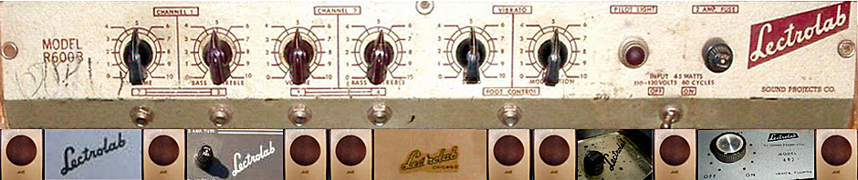
Lectrolabs are often accused of being widowmakers, and some people have gone to great trouble to add isolation transformers to these amps. I have searched the internet for every available Lectrolab schematic and have not found one without a power transformer. However there are some schematics I have not yet found. To see what I have for any model, click on the link to that model on the right side of this page, or in the pull-down menu under Amp Models near the top of the page.
For an example of an amp that LOOKS like a widowmaker see this on the R200 page:

But if you look at the schematic for that same amp:
 …you will see that there IS an power transformer.
Having said all that, ANY AMP WITHOUT A PROPERLY GROUNDED CHASSIS COULD POTENTIALLY KILL YOU. If in any doubt, and for any old amp you want to use, take your amp to a qualified tech. The widowmakers were a particularly egregious design, but no amps came with a grounded plug before the 1960′s. If you have one, and use it, modify it to be safe. By the way, it wouldn’t kill you to add a fuse to the R200B, but it might kill you if you don’t!
I have yet to see evidence that Lectrolab made a “widowmaker”. But I do not have schematics for the R203 and the R204D, both of which have the suspect 50C5 and 35W4 tubes. So the jury is out on these until someone sends me a schematic!


The schematic for the R200B does show an isolation type power transformer that supplies the voltage that powers the audio circuits of the amp. The R100B shares this basic design as well.
The tube filaments are connected directly to the incoming AC line, and just like the typical “All-American” circuits the chassis ground is isolated from the AC ground by a 0.01uF capacitor. In a typical table radio design, the chassis can be insulated by the case, knobs, etc. so that no human ever can come into contact with the metal chassis. In a guitar amp, we plug ourselves into the amp with the metal strings connected directly to the amp chassis ground. This is where the these amps run into trouble in that if we stand barefoot on a grounded floor (like a garage or basement slab), we can be shocked by whatever voltage leaks through the capacitor or worse yet if the cap fails and shorts, the full line voltage. Making sure that the Neutral side of the AC line is the side that is connected to the isolation cap will help minimize the risk.
Adding a polarized AC cord would be recommended, and adding a 3-wire cord would be even better.
Pingback: Sound Projects R203 (Lectrolab)
Pingback: Replace Death Cap with Safety Cap?
Pingback: Vintage Japanese tempo 35w4-50c5-12au6 help
Actually, the Lectrolab schematic is not isolated any better than the Harmony. The Lectrolab’s C10, represents 265k ohms of Xc from AC line to chassis. And, capacitors of that vintage were very leaky and often less than 100k ohms. Removing C10 would not affect circuit performance and would eliminate the risk.
On the Harmony amp, removing the 100K resistor would render the circuit inoperative, because the 100K resistor is the DC return for the 12AU6 cathode back to power supply.
At 100K, the max current you could send through a human body from 120VAC would be 1.2mA. Definitely an unpleasant shock, but not fatal. The 0.01uF cap of the Lectrolab serves no real purpose and poses a similar risk as it ages.
Either amplifier would be improved with the addition of a 3-wire AC cord.
Harmony amps were made by Sound Projects Company (Lectrolab’s were sold in Western Auto stores, and by the Spiegel and Alden’s mail-order catalogs)
I get your mic risk example, but I’m trying to under this statement: “Therefore your guitar strings will also connect to this circuit.” How is that? I can see the pots, the guitar cord, and pickup windings, but how are the strings in the circuit?
I have a r100b , it was shipped to me with the tubes removed, the shipper doesnt know where tgey go and they didn’t write down for me the positioning. Its 3 tubes, all the same size! Helo!!
My thoughts:
1. The best thing to do is to take it to an amp repairman who will look at the wiring inside and then know with certainty where each tube goes (assuming he can read the numbers on the tubes). If you can’t or won’t do that…
2. Unplug the amp, and see that it is turned off.
3. Google the tube numbers to figure out the purpose of each tube (preamp, power amp, rectifier)
4. One will be a rectifier tube, maybe a 35Z3 or something like that – that will go in the socket NEAREST the silver aluminum can capacitor. I am assuming that will be visible.
5. One tube will be a preamp tube, or small signal amplifier, possibly a 12SQ7 or something similar. That will go FURTHEST from the rectifier tube.
6. That leaves your power or output tube (50L6?) which will go into the middle socket.
7. Plug the amp into the wall. Do not plug in an instrument. Turn the amp on while looking at the tubes, wait a minute and hope for the low level hum of a normal old amplifier.
8. Play with the volume knob. If hiss increases when you turn it up, your are ready to plug in and see what it sounds like.
It is probable that this will work, but it is not 100% guaranteed!
9. If anything flashes, sparks, pops, sizzles, stinks, or smokes, quickly unplug it, go back to step 1. and stay there.
Thanks so very much, still a bit unclear. One tube is a 5Y3GT, one is a 6V6GT and the other is a westinghouse with the number rubbed off a _ _ Q7.
I looked closer 6V6GH. Not gt
….is the 6V6 the power tube, the 5y3 the rectifier ?
Thanks, sorry for asking questions that are obvious for many! You are kind for helping me.
Yes – 5Y3 is a rectifier, 6V6 is the power tube, and xxQ7 (probably 6SQ7) is the preamp tube.
So the 5Y3 will go closest to the power transformer, which will be the larger one, assuming there are two transformers visible. Probably closest to the can capacitor and the AC cord as well. The xxQ7 will be on the opposite side. 6V6 in the middle.
Hi!
Thanks for this site; I’ve been recently introduced to Lectrolabs and this information is vastly helpful.
I now have an R700B, and just acquired a near-mint R200B….identical to the one in the pic, down to the tube chart.
Regarding the “widowmaker” potential, I believe I understand the circuit differences between the Harmony H400 and the R200B, but I’m curious about the filament circuit’s potential for shocks.
As shown in the schematic, the heaters are fed before the T1 power transformer, this receive no isolation effect. Is it possible that a failed/failing tube could short to ground and thus energize the chassis? While a line fuse would protect the circuit, I’d hate to be part of that current path before the fuse blew.
If that’s a possibility, maybe a 1:1 transformer could be added just for the heater supply? Pretty low current draw; each tube has a heater draw rated at 0.15 amps.
Your thoughts?
And thanks again!